Electron Cloud
|
On the accelerators ... Particle accelerators increase the energy of bunches of elementary particles (electrons, protons, anti-protons, positrons, ions) for a variety of purposes. High energy physics research: Accelerated particles are smashed together or against a fixed target to study the products of the interaction and have a closer look into the basic elements of matter. Nuclear physics research: Interactions of fully stripped ions with targets to investigate the structure, interactions, and properties of the nuclei. Production of synchrotron light (extremely bright and coherent beams of high energy photons - ultraviolet and X ray) used in the study of atomic structure, chemistry, condensed matter physics, biology, and technology. Medical applications (e.g. cancer treatment with hadron bombarding). The performance of accelerators is generally related to the number of particles, packed in a little space, that they can accelerate and the energy that they can reach. High density and high energy beams are desirable! From the equation of the Lorentz force, it is clear that particles can only be accelerated with electric fields, whereas magnetic fields can only be used for guiding the particles along the desired paths/orbits. Motion of particles is relativistic, i.e. as their velocity tends to become close to the speed of light, a large increase in energy will correspond to little increase in speed.
|

|
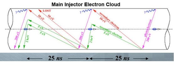 Schematic view of the evolution of an electron cloud during the bunch passages
An undesirable effect ... Electric fields present a vacuum chamber may accelerate electrons (produced by field emis- sion, photo-emission, residual gas ionization, etc) towards the wall chamber surface. If the bombarding electrons acquire enough energy, they produce secondary electrons when they hit the chamber wall, which in turn are accelerated by the electric field normal to the surface. These electrons may bombard again another surface and emit secondary electrons. If the ap- propriate combination of surface properties and electric fields are fulfilled, this bouncing back and forth between surfaces develops an electron multiplication, or multipacting effect, which creates a cloud of electrons inside the vacuum chamber. The electron cloud in accelerators is defined as an accumulation of electrons inside the beam pipe which, if sufficiently strong, can affect the machine performance by increasing the vacuum pressure, producing emittance growth, causing beam loss, cryogenic heat load or interference of the beam diagnostics..

|
Electron cloud in the Large Hadron Collider (LHC) Synchrotron radiation from proton bunches in the LHC creates photoelectrons at the beam screen wall. These photoelectrons are pulled toward the positively charged proton bunch. When they hit the opposite wall, they generate secondary electrons which can in turn be accelerated by the next bunch. Depending on several assumptions about surface reflectivity, photoelectron and secondary electron yield, this mechanism can lead to the fast build-up of an electron cloud (the animation shows simulation results by O. Brüning for 10 subsequent bunch passages, during which the pictures become red) with potential implications for beam stability and heat load on the beam screen. In view of the tight deadline for the design of the LHC cryogenic system, a crash program has been set up to measure the relevant physical quantities with and without magnetic field. For more informations see the Cern website of Ecloud phenomenon.
|
|
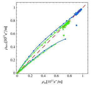
Map formalism The evolution of the longitudinal electron cloud density from bunch to bunch can be described (locally at an arbitrary chosen point along the beam path) by a simple ”cubic map” of the form: ρm+1 = α ρm + β ρm^2 + γ ρm^3 where ρm is the average electron cloud density after the m-th passage of the bunch. A similar map was next suggested and found to be reliable for all accelerator machines. The coefficients α, β, γ, extrapolated from simulations, are functions of the beam parameters and of the beam pipe features, but currently only the coefficient α has a theoretical interpretation ... then the numerical simulation is fundamental to set (after) the machine. If it were theoretically possible to estimate the coefficients without the simulation then we would have a tool that can predict the evolution of the cloud. This would be a nice outcome!
In the figure the average longitudinal electron density for different bunch populations (green: Nb = 8 ∗ 10^10, blue: Nb = 16 ∗ 10^10). The lines correspond to cubic fits. The red line corresponds to the iden- tity map ρm+1 = ρm. |
|
Cell Metal Foams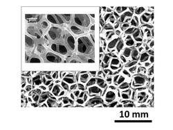
The cell metal foams are produced by vapor- (or electro-) deposition of metal on an open-cell polymer template and a final sintering step to densify the ligaments. Alternatively, they are obtained by infiltration/casting of molten metal into a solid mould, consisting of packed (non-permeable) templates of the pores. The typical structure of these materials is displayed in figure. Pore sizes in the range from 10^−4 to 10^−3 m and porosities in the range 0.8 - 0.99 are currently manufactured (For more informations see www.ergaerospace.com). These two parameters determine the material’s gas-permeability, and, together with the electrical properties of the metal matrix, its electrical properties. Metal foams have interesting structural properties (low density and weight, high (tensile and shear)- strength/weight ratio, nearly isotropic load response, low coefficient of thermal expansion).
|
Benhart J. Manufacture, Characterization and Applications of Cellular Metals and Metal Foams, Prog. Mat. Sci. 46, 559 (2001)
|
|
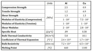
In the CERN LHC a copper-coated stainless-steel beam pipe (or liner) is kept at ≈ 20°K by active Helium cooling, and effectively handles the heat load represented by synchrotron radiation, photoelectrons, and image-charge losses. A large number (10^2 m^−1) of tiny slots are drilled in the liner wall in order to maintain the desorbed gas densities below a critical level by allowing desorbed gas to be continuously cryopumped toward the stainless steel cold bore (co-axial to the liner) of the superconducting magnets, which is kept at 1.9K by superfluid Helium.
The size, geometry and density of the pumping holes affect the beam dynamics and stability in a way which is synthetically described by the longitudinal and transverse beam coupling impedances. The hole geometry should be chosen so as to minimize the effect of trapped (cut-off) modes, and the hole pattern should be designed so as to prevent the possible coherent buildup of synchrotron radiation. Open-cell metal foams could be interesting candidate materials for beam liner design, Currently there is no a systematic study of the electromagnetic properties of the metal foams.
|

|
